
Power Scale Soaring – Part 5

by Alan Hulme
originally published in Q&EFI Magazine No 40 June 2005
Alan Hulme continues his pictorial history of PSS…
Panther
In 1992, apart from the three Scottish swing wing model fighter aircraft, we saw at both the Llandudno, North Wales and Hole of Horcum, Yorkshire meetings the initial flights of a large Grumman Panther. The model, designed and built by popular PSS flier John Vaughan, had a wingspan of 91” and an all up weight of 12½ lbs. John controlled this model via aileron, elevator, rudder and flaps and the flight pattern was awesome. (Photos 1 and 2, below)
-
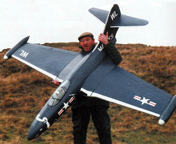
- John Vaughan lends scale to his huge Panther
-
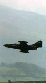
- Awesome in flight!
The fuselage construction employed a backbone of 1/8th” balsa to the outline of the side view with half formers and longerons added to each side. The fuselage was finally covered in nylon before the application of the colour scheme. Wings and tail areas were constructed from a basic built up balsa system tissue covered.
 Also at the 1992 Llandudno meeting a well finished Messerschmitt Me110 appeared. It was designed and constructed by local resident Ray Hodgkinson and had a 50” wingspan and an all up weight of just 3lbs. The wing aerofoil section was Clark Y. Construction employed a built up balsa system and controls were aileron and elevator. (Photo 3, right)
Another new design at Llandudno was Andy Conway’s latest creation in the form of an EAP Delta. This 36” span model with 2¾ lbs all up weight had elevon control. A strikingly realistic jet exhaust glow was produced by using fluorescent paint on the exhaust outlets. (Photos 4 and 5, below)
-
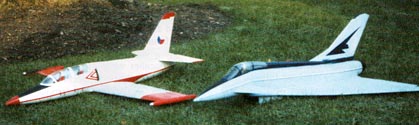
- 2 models from the Andy Conway stable, L-39 and the EAP
-
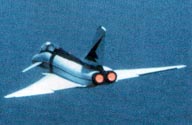
- “TURN & BURN!”
 An unusual aircraft in the form of an AD-1 American research aircraft was built around this period by Derek Price. The full sized machine was produced to test the feasibility of a novel swing wing system to establish the benefits for high speed flight. Unlike the F-111 and Tornado, the wing in this case was mounted on top of the fuselage and rotated fore and aft in a horizontal movement from the normal position, which was
at right angles to the fuselage.
The planned swing was up to 70 degrees fore and aft from the normal position. This model is still flying in the hands of the present owner, Simon Cocker, (Photo 6, left) who confirms that the model is quite stable up to a swing of 45 degrees beyond which stability is a problem.
Lancasters
 At the Leek and Moorlands 1992 meeting held near Glossop, Derbyshire, Chris Collis, from the North East of England brought his 90” span Lancaster bomber. (Photo 7, left)
The model was based on the original power plan of Chris Golds, but was modified somewhat to operate with aileron, elevator, rudder and flap control plus a bomb dropping mechanism.
 In the same year we witnessed the early flights of another Lancaster, also based upon the Golds plan, this model having been built by John Jackson from Cheshire. (Photo 8, right)
I later acquired the model and flew it in several competitions during the following years including Crook Peak, Somerset. John’s model used the wing section as shown on the Golds plan and operated with aileron, elevator and rudder control. It proved to be a most stable machine in flight.

John Plumbley’s Jaguar GR-1
During this year John Plumbley designed and built a scale SEPECAT Jaguar GR1 (Photo 9, above left ), which has since proved to be a very successful model. This 48” span aircraft of 3½ lbs weight is controlled by ailerons and elevators. Construction is of built up balsa fuselage, sheet tail surfaces and foam cored wings.
New Year
As 1993 came in so did the completion of a magnificent aircraft by Isle of Wight modeller George Dexter. George designed and constructed a mammoth model of the Saunders Roe SR45 Princess flying boat with a span of 110” and an all up weight of 15 lbs. (Photo 10, below right)
 The hull was carved from blue foam laminated to a central keel / spine of 1.5 mm ply. The fin and tailplane were cut from white foam which was covered with obechi sheet. The inner wing panels were built up using ribs, spars and stringers whilst the outer panels were cut from white foam. Ailerons, elevators, rudder and flaps were used to control the flight of this model which first flew in 1993. I was thrilled to witness this aircraft airborne at the 1995 Crook Peak, Somerset meeting. I believe the model is now on display on the Isle of Wight.
 During 1993 at the Hole of Horcum event Chris Collis turned up with yet another R.A.F. bomber aircraft, a Vickers Wellington. (Photo 11, left)
His aircraft built from foam and balsa spanned 108” and had an all up weight of 8½ lbs. The wings had white foam cores, engine nacelles were shaped from hollowed out blue foam whilst the spinners were formed of pink foam which is harder and more dense. The complete model was covered in nylon coated with SP113 resin. It was flown on several occasions in conjunction with his Lancaster.
 A meeting took place near Alnick, in N.E. England during 1993 and Bill Henderson attended with his latest own design the Rockwell B-1B American bomber. (Photo 12, right)
The construction was from blue foam covered in brown paper. Initially the wings, with Eppler 205 section, were fitted to swing but this proved to be rather a problem so they were later fixed, the aircraft being controlled via ailerons and all moving tailplane. Wingspan was 69 ½ “ and total weight 5¾ lbs.
More new models
The following year at the 1994 Clwyd gathering we saw three new models on show.
 Firstly an impressive De Havilland DH108 Swallow delta designed and built by local modeller Vic Steel. This had a span of 86” and operated with elevon control, using a mixer, and rudder control. (Photo 13, left) Alan Pierce is seen here holding the model for the camera.
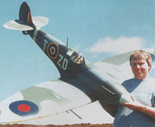
Phil Morgan entered the event with his 1/5th scale Spitfire of 96“ wingspan and a hefty 12lbs flying weight. The wing loading was 23 oz/sq. ft. (Photo 14, below)
The third new model seen at Clwyd was Steve Buckley’s high-altitude reconnaissance & stretched wing version of the Messerschmitt Me109. (Photo 15, far below)


Margaret Hulme with Alan’s new Gnat
My own new model design this year was a scale Folland Gnat finished in the colourscheme of the “Yellowjacks” – the predecessors of the Red Arrows. I enjoyed designing, building and flying this model – the plan of which was published as a free plan in a R/C model magazine.
Construction was of foam and balsa and the controls were aileron and all moving tailplane. It had a span of 39” and an all up weight of 21/2lbs. The performance of this model fully lived up to my hopes and a number of examples have been built by members of the PSSA. (Photo 16, left)
 In June 1994 Paul Sampson from North East England designed and built an 80” span model of the futuristic Northrop XB-49 flying wing. The wing was built from white foam and engine nacelles were cut and shaped from blue foam.
Paul’s model performed well (Photo 17, right) and used an electronic mixer system for aileron/ elevator. The wing section was of the reflex aerofoil type.
Another BIG One!
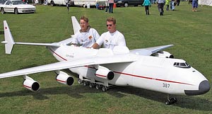
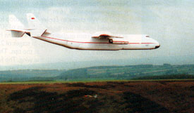
Come 1995 and another giant model appeared on the scene in the shape of Simon Cocker’s Antonov AN-225 ‘Mriya’ – the mammoth Russian cargo plane. Simon, never one to be daunted by designing, building and flying large PSS models rolled up at the Hole of Horcum event and demonstrated his latest pride and joy in relatively light wind conditions. Since then he has flown this model many times, most recently during aero towing demonstrations, before large crowds, at the Woodspring Wings, Somerset, L.M.A.Cosford and Woodvale, Southport model airshows. (Photos 18 and 19, below)
-
- AN-225 was aerotowed at the public shows…
-
- … but is just as happy off the slopes!
The wingspan of the Antonov is 18½ ft. and all up weight a massive 45 lbs. This model used 2 gallons of Copydex glue to skin the surfaces with obechi veneer, 4 litres of PVA glue to stick the foam parts together and a total of 60 meters of standard width white Solarfilm to cover the airframe.
 The second meeting of 1996, that held in Northumberland, produced a clear winner in the jet section category in Nigel Hawes North American T-2 Buckeye. (Photo 20, right)
Nigel designed and built this aircraft of distinctive shape and largish span of 70″ to a total weight of 6lbs. Using an Eppler 205 wing section and aileron, elevator and flap control the performance of this machine was outstanding. The fuselage construction consisted of a balsa box with foam decking. Wings were cut from foam and veneered.
 In June 1996 the Pendle Hill, Lancashire meeting took place. As usual it was well attended and local flier, Neil O’Hare won the event with his own design of the Concorde. (Photo 21, left)
This 70” long model with 36” span wings was built entirely from balsa for a total weight of just 4lbs. Neil used flapperons operated by a mechanical mixer to control his model which he flew in great style.
 Also taking part at Pendle was 44” span model of a North American Harvard built by Gordon Counsell from a Home of Balsa kit . It weighed just 2lbs. (Photo 22, right)
The Autumn Hole of Horcum meeting attracted a large number of entries and two quite different new designs were among the models flown.
Will Glen, from New Marske, near Middlesborough, had his own scratch built model of the Howard Hughes H – 4 Hercules “Spruce Goose“. (Photos 23 and 24, left)
 Built to 1/40th scale it had an impressive wingspan of 96″ and a total weight of 10½ lbs. Will chose an Eppler 205 section for this model with an increased thickness of 50% at the root. From outboard of the ailerons he decreased the section thickness in stages of 2.5 % down to a thickness of 10% at the tips. This produced a scale thickness to the wing.
The full sized flying boat had a wing depth of over 11 feet, enough space for a man with another on his shoulders to walk through the wing!
By complete contrast Neil McHardy entered his newly completed own design of the Saunders Roe SR A–1 prototype fighter which had a wingspan of 40″. (Photo 25)
Finally during the year a new and fully tested model by John Braithwaite was added to the PSSA plans list. This was a 106” span model of the Myasischev M-55 twin boom Geophysica. The construction was a mixture of balsawood, foam and liteply for a total weight of a mere 6½ lbs. Ailerons, elevators and airbrakes were used to control the model. (Photo 26, left)
The PSS Model
We now continue the building of a PSS model started in Part 4 and complete the construction of this model by making the wings and tail components. For the wings I suggest you make them by cutting a pair of white polystyrene wing cores, adding a balsa leading and trailing edge of medium hard ¼” strip balsa and skinning the wing cores with soft 1/16″ balsa sheet.
You first need to cut out 2 wing section templates from 1/8″ inch ply, one for the tip section and one for the centre section. A good profile is the Eppler 205. Allow a ¼” lead in and lead out at both ends of the two templates to assist in positioning the hot wire cutter. Take 2 blocks of white polystyrene foam, one for each half wing using a block which should be one inch thicker than the depth of the centre section wing rib template. Cut the blocks to the plan view of the wing half, less the thickness of the balsa leading and trailing edges. Now mark a centre line on the side of each template from leading to trailing edge and similar lines on the ends of the wing blocks. Drill three small holes along the centreline of the 2 ply templates and attach a tip and root template to the two ends of the foam blocks using tooth picks. Ensure that the centre lines on the template and foam block end match.
 Now cut the wing core to shape with a hot wire cutter and then fit the balsa leading and trailing edges using white PVA glue. Ensure that the leading edge balsa strip is of a depth ½” deeper than the polystyrene core leading edge so that when fitted it stands proud above and below the wing core by ¼”. Next butt join a sheet of 36” x 4” soft balsa to one of 36” x 3” using balsa cement and allow to dry. Repeat the process 3 more times to produce 4 butt jointed double sheets. These will be used to skin the wing cores.
To skin the cores apply an even coat of white Copydex adhesive to the underside of one wing panel and allow to dry for 10 minutes. Fit the balsa skin to the pasted undersurface ensuring the sheeting is butted up to the proud balsa leading edge. Repeat the pasting and balsa skin covering to the underside of the other wing panel and then continue by covering the top surfaces of each wing half. When dry cut off the surplus sheet overhang from behind the trailing edges and lightly sand this edge.
 Soft balsa wingtips are now added and sanded to shape to each wing half using white PVA glue. Now cut two full depth 1/8″ wide slots 3“ apart and 2” long at right angles to the root cord across the centre section of each wing half. Sand the centre section faces of each wing core to produce a dihedral, when butted together, of 1½ ” under each wingtip. Take 2 rectangular pieces of medium grade 1/8” sheet balsa 4 “ long and 1½ ” wide and fit these into the slots of each wing half with PVA glue. Ensure that these wing joiners are flat on the building surface and that the correct dihedral angle has been achieved. Allow to dry and then cut away and sand off the surplus balsa from the wing joiners so they are flush with the wing surface. Now bond a piece of 2” wide cotton bandage across the length of the wing joint above and below the wing using white PVA glue. This produces an unbreakable joint at the centre section. Now cover the wings with Solarfilm.
The lengths of sleeving are then attached to the trailing edge with the same adhesive. Ensure none of this adhesive runs onto the torque rods and if necessary apply a little Vaseline to the rod ends where they run into the sleeves. The ailerons are now hinged to the trailing edge by cutting slits centrally in the rear edge of the trailing edge and front edge of the aileron and gluing 1” by ½” nylon strip hinges into the slits using instant glue.
You should now cut out part of the foam in the centre section to locate the aileron servo between the 2 dihedral keepers and also fit two short hardwood bearers across the wing joint to accept the screws for mounting the aileron servo. It is now time to cut out from soft ¼” sheet balsa the tailplane and elevator halves as well as the single piece fin and rudder. Round off the corners with fine sandpaper and cover each component with Solarfilm. Join the elevator halves together with a U-shaped saddle of wire the ends of which are inserted into the front edge of the elevator and glued into position with 2 pack epoxy. The elevators are joined to the tailplane with 4 x 1” long by ½” wide strips of nylon hinge tape and fixed into slots cut into the rear of the elevator and front edge of the tailplane using instant glue. Fit an elevator control horn to the underside of the port elevator in line with the push rod which exits from the fuselage on the same side. Now draw a line on each side of the fuselage at the tail end along the datum line and cut a ¼” wide slot across the fuselage to locate the tailplane / elevator unit. In a similar way draw a centre line down the top of the fuselage and cut a grove 1 /4” wide to a depth of 1” to locate the fin / rudder unit. Use white PVA glue as the adhesive and ensure the tailplane and fin units are at right angles to each other. The construction is now completed. Check that the aircraft when assembled with all radio gear installed balances at a point between 30% – 33% from the leading edge of the wing, measured at the centre section. If necessary add a small amount of lead to the nose box to obtain the correct C of G location. Your model is now ready for test flying!
The following table lists plans available for some of the models described in this issue:-
|
Avro Lancaster by Chris Golds SEPECAT Jaguar by John Plumbley Folland Gnat by Alan Hulme All available via the PSSA De Havilland DH108 Swallow by Vic Steel Available as plan MW2598 from; Traplet Publications Ltd, Traplet House, Pendragon Close, Malvern, Worcestershire WR14 1GA Tel : 01684 588544
Contact us at the PSSA for more information |