
Power Scale Soaring Part 4

by Alan Hulme
originally published in Q&EFI Magazine No 39 May 2005
Alan Hulme continues his history of PSS
Moving On
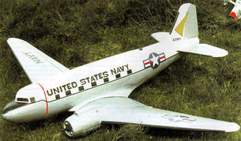
In April 1989 the Clwyd Soaring Association held their 6th annual PSS meeting on Moel Famau mountain, North Wales. It was here that we first witnessed the initial flight of Fred Jackson’s scratch built Douglas C-47 Skytrain (Dakota.) It flew as though on rails at a scale speed. This model of 80” wingspan is mainly built from white foam skinned with sheet balsa. The tail areas are built up using an open structure from balsa and the whole aircraft is covered in Solarfilm. A Clark Y wing section is used and the total weight is a mere 5 lbs. Controls are elevator, aileron and rudder.
-
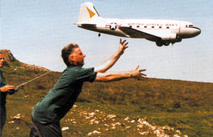
- C-47 Launch at Crook Peak
Sadly Fred passed away late last year and will be greatly missed not only in the PSS movement but as a leading member for some years with the Large Model Association. His aircraft was acquired by your scribe some years ago as witnessed in the photo showing Mike Kitchen launching for me at a Crooks Peak, Somerset meeting. It is now in the possession of Fred’s brother John who has fitted a pair of I/C 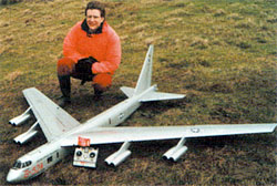 engines and it is still flying fourteen years on. (photos 1 & 2, above)
In this same year Simon Cocker introduced his new, smaller, B-52 which he kitted. Although the kit is no longer available a plan still is, which continues to sell to fliers around the globe! The model has a 108” span and employs a foam and veneer covered construction. An Eppler 205 airfoil is used and the all up weight is 8¾ lbs. Controls are rudder, elevator, ailerons and flaps. (photo 3, right)
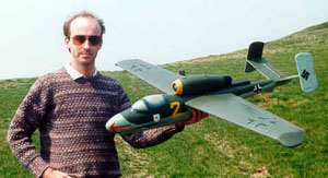
Salamander won the Rivington Pike event in ’89
Our second meeting in ‘89 was in Lancashire at Rivington Pike. Neil McHardy produced yet another own design in the form of the Heinkel He-162 Salamander which took first prize at this event. With a span of 52″ using an Eppler 205 section and total weight of only 2lbs. 10ozs it flew extremely well. (photo 4, left)

The unmistakable SR-71 Blackbird
During the year Bill Henderson, a PSSA member from Edinburgh, built and flew a model of the Lockheed SR-71 Blackbird. With its revolutionary shape it certainly created quite a stir on the slope. To quote Bill “It is a bit of a handful to fly although exciting to see in the air “ The model was built from a plan available from Richard Green of Walsall. (photo 5) Richard also offers a plan of the Boeing B-52 of 78” span, 5lbs weight constructed mainly of balsa and controlled by flapperons (ailerons and flaps combined), elevators and rudder.
The Nineties
The first event of 1990 was at the Hole of Horcum and two quite different designs were among those entered. Steve Griffiths produced his Short SB-4 Sherpa. This unusual experimental aircraft was controlled by large rotating wingtips which acted as ailerons and elevators. Steve’s model successfully used the same system. At 1/8th scale and employing an 11% NACA section at the wing root changing to an NACA 0011 at the tips it flew well. The fuselage was built around a balsa box, clad in foam and then tissue covered whilst the wings were of blue foam paper covered. Wingspan was 57” and flying weight 4lbs. (photo 6, below)
-
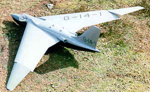
- Steve Griffiths’ Shorts Sherpa
-
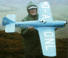
- Jack Glasby and his Sparrowhawk
The second new design at Horcum was a blue Miles Sparrowhawk 1930’s racing plane built by Jack Glasby. (photo 7, above) His model of 56” span had wings and fuselage made from foam covered in cardboard and brown paper. The wing loading was quite high at 22 oz/sq. ft, and the model needed a wind speed of around 20 mph to perform well, which it certainly did on the day.
 At the Pendle Hill 1990 meeting Ron Collins produced his Arado 234 Blitz of 72“ wingspan and 5 lbs all up weight. He used an Eppler 193 airfoil. Once again he favoured a composite foam and balsa construction and controlled the model via ailerons, elevators and flaps. In spite of a relatively low wind speed during the meeting it had a good flight. (photo 8, left)
 From Wallsend, Ian Simmonds brought along his own design of the Vought A-7 Corsair II of 4¾ lbs weight, 56“ span and using an Eppler 205 wing section. He employed a built up balsa fuselage and foam wings controlling the machine via ailerons, elevators, rudder and flaps. (photo 9, right)
 Late in ’90 the Great Orme Soaring Association held their popular PSS meeting at Llandudno. Saturday was a wash out due to high winds and horizontal rain but by Sunday morning conditions were ideal with a 15 – 20 mph wind directly onto the cliff face.
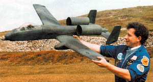
A new shape for the slope – the A-10!
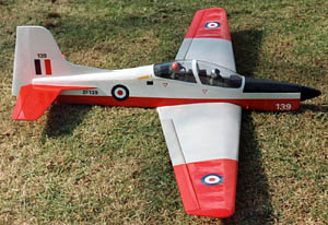
Twenty aircraft entered the fray and Phil Cooke, our current webmaster, won the competition with his own design of the new Shorts Tucano. (photo 10, above left) Two years previously, whilst at high school, Phil, for his GCSE woodwork examination, had elected to design and build this model. Built to 1/8th scale it had a 60“ span and all up weight of only 2¾ lbs which resulted in a low wing loading of just 10 oz/sq. ft. even though it was covered in Solartex rather than Solarfilm. Quite an achievement for ones first own design.
Also at this meeting – a completely different aircraft shape was seen in the form of a model Fairchild A-10 Thunderbolt II built by local modeller Garry Morgan – Jones (photo 11, above right)

Airbus A320 makes a low, slow fly by
Late in 1990 I heard from one of our members, Jack Edwards from Preston, that he had produced a model A320 Airbus to 1/20th scale from his own plans and was already working on a model of the Boeing E–3D Sentry – complete with rotating AWACS scanner! Jack is a most innovative modeller and since then has produced a number of unusual PSS designs all of which have been successful fliers.
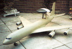
RAF ‘Sentry’ with working dish scanner!
The Airbus had a weight of around 7lbs and a span of 72”. (photo 12 right) The 73” long fuselage is of simple construction using 4 pieces of ½“ thick blue foam bonded with Copydex. This leaves a 4 in. x 4 in. space through the centre of the fuselage. After shaping, the fuselage was covered with dressmakers interfacing, similar to a strong rag tissue, using wallpaper adhesive for bonding. The wings had foam cores which were veneered. Tail members were also foam edged with balsa strips. His engine pods were formed from clear plastic bottles heat shrunk around a balsa mould.
 Jack’s 1/24th scale Sentry (above right) was of 71½” span and had a radome of 15” diameter which was rotated with a small motor at 9 revs. per minute. This aircraft flew the following year at the Glossop, Derbyshire meeting. The all up weight was 6lbs 10 oz. and controls were ailerons, elevator and flaps.
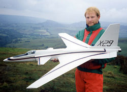
The final event of 1990 was at the Hole of Horcum and again an unusual aircraft took part. It was the Grumman X-29 experimental canard design with a forward swept wing. This model was built and flown by Ian Hammerton from Leicester. (photo 14, left)
New Venue, More New Models!
Our first meeting of 1991 was at a new venue on Gawthwaite Pike, near Ulverston, N.W England and was run by the Furness MAC. It was well attended and 30 different models were brought along. Unfortunately the windspeed was only 8–12 mph and therefore only part of the aircraft entry was flown.
David Harrhy from Aldershot entered his own design of the Sukhoi SU-25 Frogfoot. (photos 15 and 16, below)
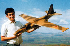
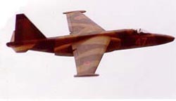
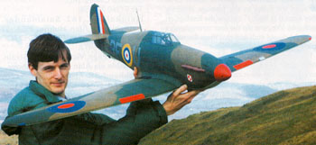 One of the larger models present was a magnificent Hawker Hurricane of 60” span and 5lbs total weight built mainly from foam by Martin Gibbs from Edinburgh. It used a simple aileron/elevator control system. (photo 17, left)
During 1991 Bill Henderson built another masterpiece in the form of a Boeing B-17G Flying Fortress. It was an own design and largely constructed from blue foam and balsa covered in brown paper. With a span of 81” it had an Eppler 205 wing section and weighed in at a commendable 7½ lbs. On its first flight, in marginal lift, it climbed well for a successful maiden sortie. (photo 18, below)
-
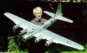
- Superb B-17 by Bill Henderson
-
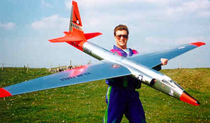
- Large scale U-2 makes the ultimate PSS Model
For the Gt. Orme, Llandudno 1991 meeting there was a good turnout of 22 models. New designs included a Lockheed U-2 of 164” wingspan built by Simon Cocker. (photo 19, above) It utilized the popular Eppler 205 wing section and tipped the scales at 22lbs. This model had veneered covered foam wings and a mainly hollowed out foam fuselage covered inside and out with veneer.
Chairman of the Gt. Orme Soaring Association, Ray Hodgkinson, entered a well finished own design of the Lockheed P-38 Lightning. (photo 20, below)
Steve Griffiths took second place in static judging with an own design Saunders Roe SR-53 and later in the year won the flying event at the Hole of Horcum with the same model. (photo below)
John Vaughan came first in both static and flying with a Vickers Valiant built from the Keith Bradshaw kit as illustrated in part 3 of this series.
-
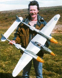
- P-38 seen at Llandudno ’91
-
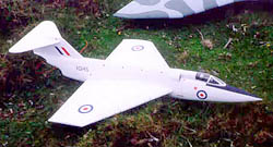
- SR-53 from the Griffiths stable
-
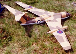
- HP Victor from Jim Strains plans
At the end of 1991 during the meeting at Pendle Hill, Lancashire we saw first hand the excellent flying capability of a model of the Handley Page Victor V-bomber designed by Northern Ireland modeller Jim Strain. (photo 22, above right) It was flown by Paul Cranshaw who won this event. This model, unlike the majority of other PSS designs, is almost entirely built up from balsa. This has produced a comparatively light total weight of only 5 lbs. giving a wing loading of 14 oz/sq. ft. The wing span is 82” and controls are via ailerons, elevators and flaps. I currently have a model built from this plan and can vouch for the excellent flying capability of this design.
Modelling Milestone
With the coming of 1992 another milestone in U.K. PSS development occurred with the introduction of not one but three ‘swing wing’ fighters from the Edinburgh boys. Ron Collins was the first to become airborne with his F-14 Tomcat of 50” span and 4lbs weight. The fuselage was a balsa box with an outer box section to form the engines. An Eppler 193 airfoil was used.
The wings were swung with a standard 3.1kg/cm torque servo driving a tie-rod to the wing. A servo saver as used in model cars was also fitted. The two other models were the General Dynamics F-111 of Martin Whitelaw and the Panavia Tornado of Andy Conway. (Photos 23 and 24, below)
-

- Martin Whitelaw poses with his original own design F-111A (far left) on the Great Orme, Llandudno. Seen here with fellow ‘swing-wingers’ Andy Conway (centre) with Tornado and Ron Collins with his F-14 Tomcat.
-
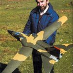
- F-111 in Landing configuration
Plan Outline
In part 3 I proposed a method for drawing up a set of plans in outline for a WW2 fighter and now follow on by suggesting the way to build a simple airframe to fit within the plan outline.
The fuselage, with the exception of the nose portion is made from solid white polystyrene foam, skinned externally with soft 1/16th inch balsa sheet. To build this first take two sheets of 3 inches thick polystyrene 20 inches long by 4 inches wide. Fasten these together one above the other to form a block from which we shall cut the fuselage. You can pin the two pieces together with cocktail sticks.
Now trace and cut out 2 pairs of templates from thin ply using your outline plan, one pair for the side view and the other for the plan view. Draw a datum line from nose to tail on each template taken from the positions of the datum lines on your plan. Remember that the templates do not include the areas of the front 6 inches of the plan. This portion will be made later using built up balsa construction.
As described in part 2 of this series, when describing “lost foam” fuselage construction, drill small holes in the 4 templates along the datum lines and attach the 2 side templates to the foam block ensuring the datum line is positioned along the joint line of the blocks. Cut out the side view shape with a hot wire cutter and repeat the process using the 2 other templates for the plan view. Ensure that the datum line on these runs down the centre of the blocks viewed lengthwise.
You may now sand the polystyrene to an acceptable cross section shape referring to the cross section templates on you 1/72 scale plan for guidance. We now need to remove some of the polystyrene from the lower block to leave a space in the fuselage to clear the aileron servo which will be attached to the centre section of the top surface of the wing. To assist in this separate the two fuselage pieces and cut out the polystyrene from the lower half. Whilst separated cut a grove down the length of the bottom side of the top block running from nose to tail ensuring that the grove runs to the outer edge of the fuselage at the tail. Fit into this grove a length of plastic outer snake which will accommodate the inner snake connection between elevator servo, to be mounted in the balsa nose section, and the elevator control horn. You should now rejoin the two fuselage parts using white PVA glue and allow to dry overnight.
The wings will be attached to the fuselage with rubber bands and 2 – ¼ inch dia. dowels. For this purpose we need to drill holes through the polystyrene across the fuselage in the lower block in positions shown on the sketch. Now cut 4 – 1mm ply strengtheners 1 inch square and drill a ¼ inch diameter hole through each to accommodate the dowel. Cut two lengths of dowel to fit through the holes in the fuselage ensuring they extend at least 1 inch outside the fuselage on each side. We now slip the 4 strengtheners onto the dowel ends and glue them flat to the foam fuselage.
The fuselage is now covered with soft 1/16 inch thick sheet balsa. To assist in covering the curved areas the sheet can be wetted with water. Use white PVA glue as an adhesive and wrap masking tape or rubber bands around the sheeted areas until the glue is dry.
The front section is now built up in the conventional manner using strips of 3/16.inch and 1/2inch balsa between the two formers. Add triangular cross section strips of balsa behind the front former and in front of the back former to strengthen the vertical joints between formers and side sheeting. Fit 2 hard balsa servo rails across the nosepiece to accommodate the elevator servo leaving sufficient space in front to fit the receiver battery. The miniature receiver fits under the servo. The nose block and spinner are built up from laminations of ¼ inch sheet balsa and the middle of the rear two laminations are cut out to accommodate part of the Rx battery. The block is now fixed to the front section with 2 pack epoxy glue and after drying it is sanded to align with the nose section. You can now fit the front section to the rear fuselage using epoxy glue. The fuselage is now covered in Solarfilm. This completes the fuselage. In part 5 we shall complete the construction of the model.
The following table lists plans available for some of the models described in this issue:-
|
Boeing B-52 – 108″span by Simon Cocker, 14 Bank Side Court, Alsager, Stoke on Trent, Staffordshire, ST7 2DN Heinkel He-162 Salamander (by Neil McHardy) Handley Page Victor (by Jim Strain) both via Alan Hulme, 52 Mountway, Waverton, Chester CH3 7QF Lockheed SR-71 Blackbird by Richard Green, 57A Long Lane, Newton, Great Wyrley, Walsall WS6 6AT
Contact us at the PSSA for more information |